Interference colour. How is it formed?
5 polariser + anisotropic mineral (general case) + analyser
5.2 What happens when the waves from the crystal arrive
at the analyser?
En la pantalla anterior teníamos dentro del cristal a dos ondas vibrando en planos perpendiculares con la misma dirección de propagación y con un determinado desfase. Para analizar este desfase lo que se puede hacer es provocar la interferencia de estas ondas, para lo cual basta hacerlas vibrar en un mismo plano. Y esto es lo que se consigue al intercalar el analizador.

Vertical drawings
In the left part of the figure, the waves have been drawn travelling within the plane of the screen, with vertical direction of propagation.
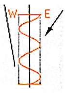 POLARISER
The wave from the polariser:
-vertical direction of propagation
-horizontal direction of vibration, (W-E) within the plane of the screen.
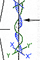 MINERAL
When a polarised light wave arrives at an anisotropic crystal in a general position it experiences double refraction. The initial incident wave splits into two polarised waves which vibrate in perpendicular planes and which, we will imagine to be moving with the same direction of propagation (in this figure, vertical).
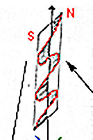 ANALYSER
The wave from the analyser:
-vertical direction of propagation
-horizontal direction of vibration, (N-S)perpendicularly
to screen.
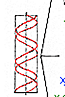
FROM MINERAL TO ANALYSER
There were two waves inside the crystal vibrating in perpendicular planes with the same direction of propagation and a certain phase difference. In order to analyse this phase difference, an interference in the waves can be provoked, i.e. by making them vibrate in the same plane. This is what is achieved by interposing the analyser.analizador.
Horizontal drawings
In the right part of the figure, the waves have been drawn travelling perpendicularly to the screen.
The changes that the waves experience in the polarising microscope are better represented in diagrams transverse to the direction of the rays, i.e. by drawing the rays propagating in a perpendicular direction to the plane of the diagram, just as the waves would be observed through the eyepiece of the microscope.
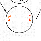
POLARISER
The wave from the polariser (horizontal in the diagram) is represented by the vector WE.
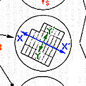
MINERAL
Two waves in the mineral, in the two directions of vibration permitted (XX´ and YY´).
.
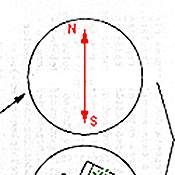
ANALYSER
The wave from the analyser (vertical in the diagram) is represented by the vector NS.
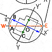 FROM POLARISER TO MINERAL
In general, for each direction of incidence of light on the crystal, the crystal's atoms vibrate in only two directions, which are perpendicular to each other.
The wave from the polariser (horizontal in the diagram) is represented by the vector OA. This wave will divide in the two directions of vibration permitted in the crystal (XX´ and YY´), represented by the vectors OB and OC.
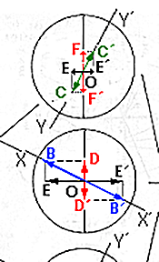
FROM MINERAL TO ANALYSER. I
When each wave from crystal (BB´and CC´) arrive at the analyser, this wave will have different direction of vibration from the analyser and, in order to pass through this polaroid plate, they will each have to divide again into another two waves, in the plane of vibration of the analyser, DD´ and FF´, and in the plane perpendicular to it, EE´. The latter will be annulled as their direction is perpendicular to that permitted by the analyser.
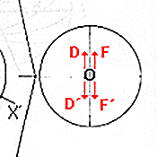 FROM MINERAL TO ANALYSER. II
As a result, we will have two waves (DD´ and FF´) travelling in the same direction and vibrating in the same plane (that of the analyser). These two waves must interfere and their interference will be positive (constructive) or negative (destructive) according to their phase difference, which will depend on the phase difference introduced by the crystal.
But when are they constructive and when destructive?
Index | Introduction | PPL | XPL ortos | Interf colour | Int. c. formed? | Previous | Next | Top